03-Sep-2022
Want to know about the steering system. Read this ultimate guide
Are you wondering about driving a car?
Though it’s a herculean task if you are not a driver, let me tell you it’s not impossible.
Now I have a question for you
Have you seen a car without a steering system?
Ah! I am not kidding but probably not.
The steering system is the only thing that gives you direction on where to move your vehicle, isn’t.
Everybody will without a doubt be anxious to think about the directing framework. Here in this article, they will think about the guiding framework, its parts, capacities, and furthermore how it works.
Let’s come to the topic
What is a Steering system?
In straightforward words, the controlling arrangement of your vehicle is everything from the guiding wheel to the directing shaft, rack, and pinion (otherwise called the gearbox), right to the linkage associated with the actual wheels.
It is otherwise called the guiding framework, in autos, controlling wheel, pinion wheels, linkages, and different parts used to control the course of a vehicle's movement.
The framework contains a water-powered supporter, which works when the motor is running and supplies the vast majority of the essential power when the driver turns the wheel.
It’s important to understand the parts/components a steering system has
Types of the steering system
There are two kinds of guiding frameworks accessible. They are:
- Pressure driven
- Electric/electronic
1. Pressure-driven Steering framework:
Pressure-driven force guiding frameworks work by utilizing a water-powered framework to increase the power applied to the controlling wheel contributions to the vehicle's directed (typically front) street wheels. This is the main part of a particular steering system.
The water-powered pressing factor regularly comes from a generator or turning vane siphon driven by the vehicle's motor.
This is known as the Hydraulic Steering framework.
2. Electric/electronic Steering framework:
- The Electric/Electronic Steering framework is otherwise called the force controlling framework.
- In engine vehicles, a force-controlling framework assists drivers with directing the vehicle by increasing guiding exertion expected to turn the controlling wheel, making it simpler for the vehicle to turn or move. Electric force guiding frameworks utilize electric engines to give help rather than water-driven frameworks.
Parts/Components of a Steering framework:
The parts of a controlling framework are recorded underneath. They are:
1. Guiding wheel
2. Guiding segment or shaft.
3. Controlling stuff
4. Drop arm or pitman arm
And many more
But in this guide, I will cover some important parts
1. Controlling wheel:
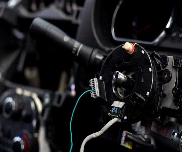
The controlling wheel is the control wheel to guide a vehicle by the driver. It contains a traffic marker switch, light switch, wiper switch, and so on. It is additionally called a driving wheel or a hand wheel is a sort of directing control in vehicles.
2. Directing segment or shaft:
The Steering section otherwise called the shaft is fitted inside the empty controlling segment. At the point when the guiding wheel is turned, the directing shaft will likewise be pivoted. Because of this, the movement is sent to the guiding box.
3. Guiding stuff:
The pitman's arm is splined to the guiding gearbox rocker arm toward one side and the opposite end is associated with the drag connected by a rotating conjuncture.
4. Drop arm or pitman arm:
- At the point when the controlling wheel is turned right or left the pitman sends the movement it gets from the directing gearbox to the tie bar. A 'drop pitman arm' is utilized to address the control when a vehicle has a suspension lift.
- Now, the main question arises like
- How the entire steering system works. Keep on reading!
How does the steering system work?
There is a step-wise step process. Let’s discuss this
- Step 1 Directing framework will change over the rotational movement of the controlling wheel into the rakish turn of the front wheels.
- Step 2 Directing wheel turns the guiding segment.
- Step 3 The directing gearbox is fitted to the furthest limit of this section. Consequently, when the wheel is pivoted, the cross shaft in the gearbox sways.
- Step 4 The cross shaft is associated with the drop arm. This arm is connected through a drag connected to the controlling arms.
- Step 5 Directing arms on the two wheels are associated by the bind poles to the drag connect.
- Step 6 At the point when the directing wheel is worked the knuckle moves forward and backward, moving the guiding knuckle are associated with one another.
One finish of the drag interface is associated with the tie bar. The opposite end is associated with the finish of the drop arm.
This is all about the guide of the whole steering system

SEO and Content Writer
I am Drishan vig. I used to write blogs, articles, and stories in a way that entices the audience. I assure you that consistency, style, and tone must be met while writing the content. Working with the clients like bfc, varthana, ITC hotels, indusind, mumpa, mollydolly etc. has made me realized that writing content is not enough but doing seo is the first thing for it.
Join Our Newsletter
Subscribe to our newsletter to receive emails about new views posts, releases and updates.
Copyright 2010 - 2026 MindStick Software Pvt. Ltd. All Rights Reserved Privacy Policy | Terms & Conditions | Cookie Policy